日本語
 한국어

CMM Inspection for CNC Machined Parts: Process, Accuracy & Reports
A CNC-machined part can meet basic size requirements yet fail because a hole pattern is misplaced or two axes are misaligned. CMM inspection measures geometry in three dimensions and evaluates it against the drawing, CAD model, and geometric dimensioning and tolerancing (GD&T) requirements. Its real value is evidence that critical features were measured from the correct datums.
CMM Inspection at a Glance
- A coordinate measuring machine records X, Y, and Z positions and calculates features such as planes, circles, cylinders, axes, and profiles.
- It is especially useful for datum-based GD&T, complex geometry, and relationships between features.
- Results still depend on probe access, fixturing, temperature, alignment, programming, and uncertainty.
What Is CMM Inspection
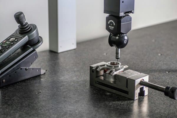
CMM inspection is dimensional verification performed with a coordinate measuring machine. A tactile or non-contact sensor records points on the component, and metrology software compares the resulting geometry with nominal dimensions and tolerance zones. Touch-trigger probes suit holes, planes, and feature locations; scanning probes collect dense data for form and profile; optical sensors help with small or delicate features.
Alignment is fundamental. Before evaluating position or profile, the program must establish the datum reference frame specified on the drawing. If the wrong surface or datum order is used, the result may not represent design intent.
Practical example: A mounting plate can have four correctly sized holes but still fail because the pattern is misplaced. A CMM can construct datums A, B, and C, measure the hole axes, and evaluate true position-something a caliper cannot reliably do.
How Does the CMM Inspection Process Work
Step 1: Review the released files
The inspector confirms the drawing revision, CAD model, GD&T standard, datums, critical characteristics, and report format. File conflicts must be resolved before programming.
Step 2: Select the measurement method
Part size, tolerance, geometry, material, probe access, and required uncertainty determine whether to use touch probing, scanning, optical measurement, or another gauge.
Step 3: Stabilize and fixture the part
The part and environment should be thermally stable. Fixturing must prevent movement without distorting thin walls or soft materials, and measured surfaces must be clean.
Step 4: Qualify the probe and align the datums
The stylus is qualified with a calibrated reference artifact. The program then measures datum features in the order defined by the drawing.
Step 5: Measure and evaluate features
The CMM collects points with a defined strategy. Software constructs features and evaluates size, location, orientation, form, runout, or profile.
Step 6: Review and issue the report
A reviewer checks unexpected results, coverage, alignment, and settings before releasing the report. A failed result should be verified before disposition.
What Can a CMM Measure
| Requirement | Typical examples | Why CMM helps |
|---|---|---|
| Size and distance | Diameter, width, height, center distance | Produces repeatable numerical results in one coordinate system |
| Location | Hole position, bolt circles, feature spacing | Relates multiple features to common datums |
| Orientation | Parallelism, perpendicularity, angularity | Evaluates planes and axes in three dimensions |
| Form | Flatness, straightness, circularity, cylindricity | Uses multiple measured points to estimate geometric form |
| Profile and runout | Curved surfaces, compound contours, rotating features | Compares complex geometry with defined tolerance zones |
CMM inspection has limits. Tactile probing may not suit flexible parts, inaccessible features, tiny openings, or rough surfaces. Surface roughness, thread integrity, hardness, coating thickness, and material composition normally require dedicated instruments. A strong plan combines tools instead of forcing every requirement onto one machine.
When Should You Request CMM Inspection
CMM measurement is a good choice when:
the drawing contains datum-based GD&T;
several features must be related in three dimensions;
the part has complex contours, angled bores, or multi-sided geometry;
mating, sealing, bearing, or alignment features are function-critical;
a first article inspection (FAI) or traceable dimensional record is required;
dimensional drift must be monitored across a production run.
For a simple part with generous tolerances and accessible dimensions, calibrated hand tools or gauges may be faster and more economical. Specify CMM where it adds useful evidence; unnecessary full inspection adds programming time and cost.
How Accurate Is CMM Inspection
There is no universal CMM accuracy. Results depend on machine specification, measured length, sensor, stylus, calibration, temperature, fixturing, point strategy, surface condition, and software. ISO 10360-2:2009 defines acceptance and reverification tests for Cartesian CMMs using contact probes for linear measurements.
Uncertainty is especially important near a tolerance limit. ISO 14253-1:2017 provides decision rules that account for it. A result of 9.999 mm is not meaningful alone; the tolerance, uncertainty, and acceptance rule are also needed.
Metrology note: Machining tolerance and CMM accuracy are different specifications. A supplier's ability to machine a feature to ±0.05 mm does not mean the CMM accuracy is ±0.05 mm, and a precise CMM does not make an unstable machining process capable.
What Should a CMM Inspection Report Include
A useful report shows what was measured, against which requirement, and under what conditions. Request:
job, part, serial or lot identification, plus drawing and CAD revision;
balloon number, nominal value, limits, actual result, deviation, and status;
datum reference frame and applicable GD&T modifiers;
CMM ID, program and revision, inspection date, and reviewer;
calibration traceability, acceptance rule, and notes for any recheck or concession.
For North American drawings, ASME Y14.5-2018 (R2024) is the authoritative source for stating and interpreting GD&T. Identify the standard and edition on the drawing rather than leaving the convention to assumption.
CMM Inspection for PCBgogo CNC Machining Projects
PCBgogo's CNC capabilities include milling, turning, and mill-turn machining with 3-axis, 4-axis, and 5-axis equipment. Dimensional inspection uses CMM measurement, calipers, and optical microscopes according to feature type. First article reports and material certificates are available on request.
The published CNC milling capabilities list general tolerances of ±0.1 mm for 3-axis and 4-axis milling and ±0.05 mm for 5-axis milling. These are machining references-not guarantees for every geometry or statements of CMM accuracy. Critical tolerances require review based on material, geometry, finish, and inspection access. A reliable quote must cover both making the feature and proving conformance.
PCBgogo - Precision Custom CNC Machining
Save time and money with reliable CNC milling & turning. Get tight?tolerance custom parts, streamlined sourcing, and consistent production quality for your projects.
Get a Free Quote >
How to Prepare Your CNC Files for Reliable Inspection
For critical tolerances, send a 3D CAD model plus a controlled 2D drawing identifying:
the GD&T standard, edition, and datum scheme;
critical-to-function dimensions and tolerance zones;
material, post-processing, and whether dimensions apply before or after finishing;
sampling level, FAI, dimensional report, or CMM report requirements;
any special acceptance rule or report template.
Apply tight tolerances only where function demands them and use general tolerances elsewhere. This clarifies inspection and can reduce cost.
Frequently Asked Questions
Is CMM inspection required for every CNC machined part
No. Geometry, tolerance, risk, and documentation needs determine the method. Simple dimensions may be checked more efficiently with conventional gauges.
What is the difference between a CMM report and an FAI report
A CMM report contains machine-produced results. An FAI report is broader and may combine CMM data with manual measurements, material records, and process documentation.
Can a CMM inspect Geometric Tolerances?
Yes, when the machine, sensor, program, and uncertainty are suitable. Correct datum construction and interpretation remain essential.
Should I provide both CAD and a 2D drawing
Yes. CAD supplies nominal geometry; the drawing communicates tolerances, datums, notes, and reporting requirements.
Get CNC Parts with Documented Dimensional Verification
CMM inspection is most valuable when it turns design intent into traceable evidence. Define datums, tolerances, sampling, and the report format before production. PCBgogo can review your files and quote an appropriate CNC and inspection approach.
Upload your files and state "CMM report required" with the characteristics that must be reported.