Introduction:
SMCs are a major part of PCBs, those along with THCs are the two basic types of components used in printed circuit boards. However, you’ll find SMCs more widely used as opposed to THCs. Partially because of the contrast in assembly time and cost along with reliability and quality.
PCBgogo is a major PCB manufacturing company in Shenzhen that manufactures and assembles PCBs using surface mount components.
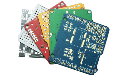
Image Courtesy: pcbgogo.com
Here we’ll briefly discuss what SMCs are, how they are constructed, and why they are used more widely as opposed to THCs.
What are SMCs?
Content
· 1 What are SMCs?
· 2 SMCs vs. THCs
· 3 What is Surface Mount Technology (SMT)?
· 4 Component Packaging
· 5Application of Solder Paste and Stencil Creation
· 6 Pick-and-Place Machine
· 7 Reflow Soldering
SMC’s are Surface Mount Components, also known as SMDs (Surface Mount Devices). Surface mount components are those which are mounted directly onto the surface of a PCB with the help of surface-mount technology (SMT). They are typically smaller and are ideal for use in devices that are smaller or flat.
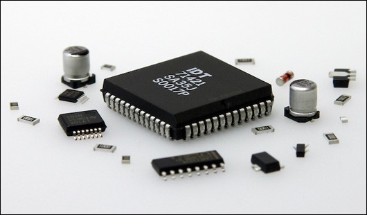
Image Courtesy: pcbgogo.com
SMCs vs. THCs
Surface mount components have largely replaced through-hole components. Surface mount components are generally flatter and smaller as compared to through-hole components which have lead protruding from their sides. THCs require holes to be drilled in the PCB through which the leads of the components can be passed through and soldered to the opposite end (hence known as thru-hole technology)
However, the presence of these holes reduces the mechanical strength of the board making it prone to damage and reduces its reliability. PCBs assembled using thru-hole technology are also larger in size as the components are generally larger and so they cannot be used in smaller devices. This along with the increased time and cost in manufacturing them makes it a less preferred method of assembly.
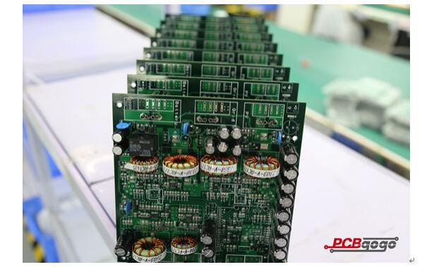
Image Courtesy: pcbgogo.com
What is Surface Mount Technology (SMT)?
SMT as we’ve mentioned before is the name of the technology used to assemble surface mount components onto PCBs. The assembly and manufacture of SMCs involves the following:
1. Component packaging
2. Application of solder paste and stencil creation
3. Pick-and-place machine
4. Reflow soldering
1. Component Packaging
Surface mount components are generally flat and are directly mounted and soldered onto the PCB board. This gives PCBs the additional advantage of being able to have SMCs mounted on both sides of the board. Particularly, if you’re looking to use them in smaller sized gadgets or devices. Surface mount components are generally selected based on the application it will be used in and the space available on the circuit board.
As far at the packaging of components is concerned, they must be packaged in a way that protects them from any potential damage. SMCs are usually packaged and transported in the form of tapes, reels, and trays.
Essentially, SMCs will be placed on taped and then wound into reels. To prevent the components from falling off the tape is usually sealed off from the top with a transparent film. The component packages are then shipped in antistatic plastic rails.
Smaller and medium-sized packages are usually packaged on tape and reels whereas larger packages are packaged in trays which are also sealed with a transparent film from the top.
AT PCBgogo SMT parts are packaged in the form of cut tape, trays, tubes, reels, and partial reels to name a few.
2. Application of Solder Paste and Stencil Creation
Before surface mount components are mounted onto the PCB, solder paste must be deposited on designated areas of the circuit board (onto copper pads). The amount deposited must be carefully calculated, anything below the required amount may lead to dry solders and anything above the amount required may lead to solder bridging.
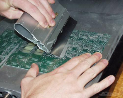
Image Courtesy: pcbgogo.com
In order to deposit solder where required, a stencil is used with openings made to direct the solder paste. Usually, a stencil is aligned onto the PCB after which a small quantity of solder paste is added to one end of the stencil after which a squeegee is used to force the solder paste through the cutouts in the stencil. Once the solder paste is deposited the stencils are removed. PCBgogo uses stencils with and without frames which usually offered free.
3. Pick-and-Place Machine
The next step which involves the placement of components is usually automated via pick-and-place machines instead of done manually. A pick-and-place machine will pick up the components from the tape or tray they were packaged in and rotate them to the correct orientation. Next, the correct position of the component will be located and the components will be placed over the solder paste deposited in the previous step.
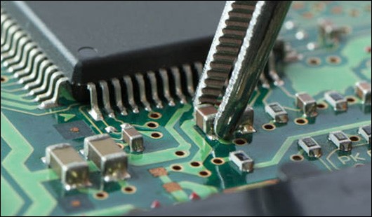
Image Courtesy: pcbgogo.com
This process could be done manually with the help of tweezers but it is not suitable for finer, smaller components and the precision of the placement of components may not be the same as when done via a pick-and-place machine.
4. Reflow Soldering
The final step is ‘reflow soldering’. Here the board with the components carefully placed is passed on to a reflow soldering machine. Here, with the help of controlled heating, the solder is melted and then solidified to form solid solder joints. Timing and temperature play a very important role here, any deviation from the required settings may result in poor soldering.
Conclusively we can say that the SMC assembly process is an intricate one, each step is equally important and negligence at the smallest level can lead to major errors. This is why it is important to make sure the PCB company you’ve hired is skilled in the assembly process.
This article is originally published on electronicslovers.com and authorized to reprint on PCBgogo.
The original link: https://www.electronicslovers.com/2020/12/surface-mount-vs-through-hole-components-assembly-process.html


