A Guide to PCB Layout & How to Place Your Components | PCBGOGO
Introduction:
Once you’ve designed the schematic for your PCB, the next step is turning it into a reality. PCB layout is a very exciting process. Have you ever wondered how is it done? How are the tiny intricate components placed? Well lucky for you we will explain just that for you!
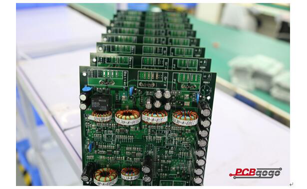
Some things to keep in mind:
There are a couple of things to keep in mind before we continue including:
· PCB layout is an art form. Every engineer will design a PCB layout from a schematic a unique way with unique characteristics. People even get creative with lining the traces and vias. The entire placement of components is based on your design perspective.
· Remember to think about the manufacturing process before you design your PCB. Consider component orientation so as to make your board easier to install and test. Secondly, consider the placement of components with relation to one another. For example, if you place larger components in front of smaller ones then you’ll end up with a poorly soldered board.
· Think about your routing beforehand. Leave enough room between components so routing is easy to complete. If not, you may have to start your layout all over again from scratch.
· Before you start, make sure to keep an outline of the entire process inside your head, this will help you complete the process hurdle-free, and also provide a foundation to work from. There are three basic steps in the process we will discuss here.
PCB Layout Process:
Now let’s dive into the PCB layout process. Here we will discuss some practical PCB layout strategies.
Step 1: Turning Your Schematic into a Board Layout
To convert your schematic to a PCB layout you will have to:
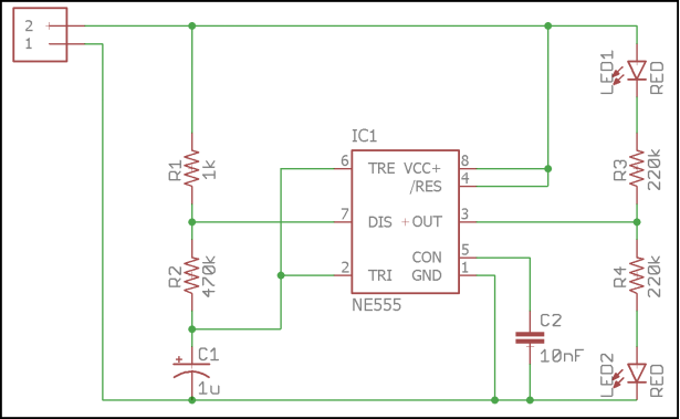
1: First, open your schematic project from the Autodesk EAGLE Control Panel.
2: Select the SCH/BRDicon at the top of the interface. This will start generating your PCB layout from the schematic.
3: If you get a warning dialogue saying that the .brd file doesn’t exist and that you want to create it from your schematic, click ‘Yes’.
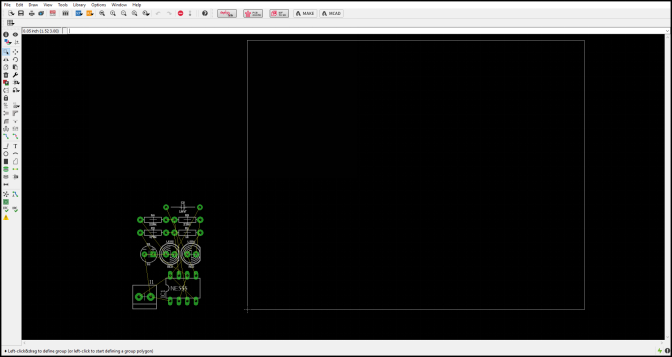
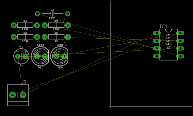
That’s all! Now you should have a second Autodesk EAGLE window open. This is the black PCB layout canvas which you will use to start your design.
There are a few things you need to take note of including:
· The white square outline is the physical dimensions of your board layout which you will be placing all your components in.
· Currently all your components will probably be resting outside of this outline, you will process by moving them into the area.
· You will also notice a bunch of lines connecting between your components. There are ‘airwires’which will help you understand your component connectivity.
Step 2: Placing and Rotating Your Components:
How you place your components is ultimately up to you. Usually engineers will first place all their edge components first, such as USB ports and power jacks. Next, the largest components are placed. Consider a case in which you have to place an IC with a large number of pins, you can place this first by following the steps provided.
1: Select the Move took on the left side of the interface.
2: Next, left click the component and drag it into your board outline. You will notice that all of the airwires also move with this component.
3: Now you can rotate the component as much as you like by right-clicking.
4: Finally, left-click to place your component where you want.
Once you’ve got the biggest part down placing the smaller components gets easier. The rest of the placement is entirely up to you. Here are some tips we have to help you out!
Tips for Component Placement:
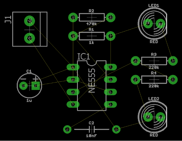
· Try to keep your connections as short as possible to minimize the length and criss-crossing of airwire connections
· While adjusting your components placement, also adjust the airwires constantly. You can use the Ratsnest tool on the left-hand side of the interface to redraw all your airwires whenever you place a new component.
· Remember to avoid overlapping parts and leave plenty of room between components at all times. If not, you may end up with a short circuit.
Step 3: Resizing Your Board Shape:
By now all your components should be placed onto your board. With steady practice, you’ll get the hang of it real quick! Now only one step remains i.e. defining the dimensions of your board layout.
For this, simply follow the provided steps:
1: Select the Movetool on the left-hand side of your interface.
2: In order to adjust the size of the corners left click on the top right corner of your PCB layout, then drag that point towards your components.
3: To finalize this corner, left click once again. Repeat this process for the remaining corners.
Once completed, you will end up with a much smaller PCB layout with all the components efficiently packed. And that’s all! You have successfully completed your PCB layout process.
PCBGOGO, a professional and trustworth PCB and PCBA manufacturer with over 10 years.
