An Introduction to Aluminum PCBs by PCBGOGO
Aluminum PCBs are printed Circuit Boards which contain a thin layer of conductive dielectric material. They are also known as Aluminum Clad, Aluminum base, MCPCB (Metal Clad Printed Circuit Board), IMS (Insulated Metal Substrate), Thermally Conductive PCBs etc. Aluminum PCBs were developed in the 1970s, soon after which they’re applications increased dramatically. The first application was their use in Amplification Hybrid Integrated Circuits. Now they are being used at a large scale due to which it is necessary for us to have an idea of Aluminum PCBs and their importance.
Structure of Aluminum PCBs:
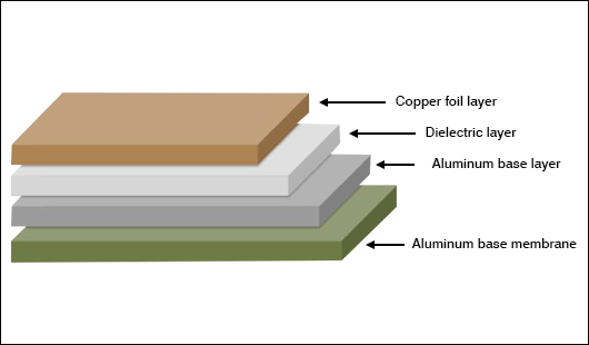
Aluminum PCBs are aluminum based CCLs (CCL is a type of base material of PCBs). AluminumPCBs are actually quite similar to FR4 PCBs. The basic structure of Aluminum PCBs is four layered. It consists of a layer of copper foil, a dielectric layer, an aluminum base layer and aluminum base membrane.
-
Copper Foil Layer: The copper layer used is relatively thicker than normal CCLs ( 1oz-10oz). A thicker layer of copper means a larger current carrying capacity.
-
Dielectric Layer: The Dielectric layer is a thermally conductive layer and is around 50μm to 200μm thick. It had a low thermal resistance and it suitable for its application.
-
Aluminum Base: The third layer isthe aluminum base which is made up of aluminum substrate. It has a high thermal conductivity.
-
Aluminum Base Membrane Layer: Aluminum base membrane is selective. It has a protective role by keeping the aluminum surface safe from scraping and unwanted etching. It is of two types i.e. Lower than 120 degree or around 250 degrees (Anti high-temperature)
Performance of Aluminum PCBs:
-
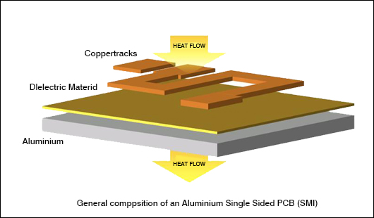
Thermal Dissipation: The performance of aluminum PCBs while dissipating heat is quite well as compared to ordinary FR4 PCBs. For example, a FR4 PCB that is 1.5mm thick will have thermal resistance of 20-22 degrees per watt whiles a aluminum PCB 1. 5mm thick will have a thermal resistance of 1-2 degrees per watt.
-
Thermal Expansion: Each substance has its own coefficient of thermal expansion. The CTE of aluminum (22ppm/C) and copper(18ppm/C)is quite close. Since aluminum PCBs work well in terms of Thermal dissipation they do not have severe expansion or contraction issues. They work excellently and are durable and reliable.
-
Dimensional Stability: Aluminum PCBs show dimensional stability and stable size. For example, when they are heated from 30-140 degrees, their size only had a change by 2.5%-3.0%.
-
Others: Aluminum PCBs can be used in power device surface mount technology. They are effective for use in circuit design because of their performance in terms of thermal expansion of circuit design. They help to prolong products shelf life and product power density. They are also extremely reliable. They can help to shrink the overall volume of the product and is also a cheaper option. They show electromagnetic shielding and high dielectric strength.
Classification of Aluminum PCBs: Aluminum PCBs are essentially divided into three categories.
1: Universal Aluminum PCB: The dielectric layer used here is made up of epoxy glass fiber pre-preg.
2: High Thermal-Conductive Aluminum PCB: The dielectric layer is made up of epoxy resin. The resin used must have high thermal conductivity.
3: High-frequency Aluminum PCB: The dielectric layer is composed of polyolefin or polyimide resin glass fiber pre-preg.
Manufacturing Difficulties of Aluminum PCBs:
The manufacturing process for nearly all aluminum PCBs is essentially the same. Here we will discuss the major manufacturing processes, the difficulties and their solutions.
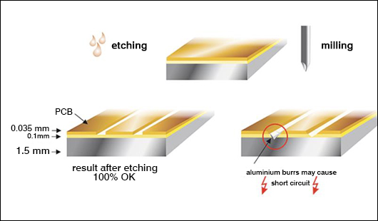
1: Copper Etching: The copper foil used in Aluminum PCBs is comparatively thicker. If the copper foil is over 3oz however, the etching requires width compensation. If it is not according to the demand of the design, the trace width will be out of tolerance after etching. Therefore the trace width compensation should be designed accurately. The etching factors need to be controlled during manufacturing process.
2: Solder Mask Printing: Due to the thick copper foil there is a difficulty in solder mask printing of aluminum PCB. This is because if the trace copper is too thick then the image etched will have a large difference between trace surface and base board and solder mask printing will be difficult. Therefore, the two-time solder mask printing is used. The solder mask oil used should be of good quality and in some cases the resin filling is done first and then solder mask.
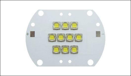
3: Mechanical Manufacturing: The mechanical manufacturing process involves mechanical drilling, molding and v-scoring etc. which Is left on internal via. This tends to reduce electrical strength. Therefore, the electric milling and professional milling cutter should be utilized for low-volume manufacturing of products. The drilling parameters should be adjusted to prevent burr from generating. This will help your mechanical manufacturing.
PCBGOGO the Best PCB Manufacture in China is Offering PCB and Assembly services at Low Price.
