Open up any electronic device within your reach and you’ll find Printed Circuit Boardsfitted inside. On the surface of the board, you’ll find a number of smaller devices/components. Traditionally, these components would be connected to the board via wire leads, also known as the thru-hole technology method. However, this method is not suitable for smaller-sized devices in which you have to fit a number of components onto one board.
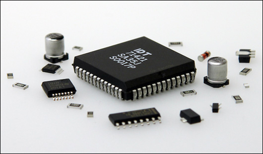
Image Courtesy: pcbgogo.com
A new method evolved which makes use of “Surface Mount Technology”, instead of using wire leads, the components are directly mounted to the surface of the boards. It is now the most commonly used technology in PCB manufacturing.
What Is Surface Mount Technology (SMT)?
Surface Mount Technology as we’ve mentioned before allows the direct mounting of components onto the printed circuit board. The components which can be mounted onto the PCB are known as surface-mount devices (SMD).
Although this method is now more widely used as opposed to thru-hole technology, both technologies can also be used side-by-side on the same board. There are certain components such as large transformers and heatsinked power semiconductors that are not suitable for surface mounting, and so are connected using thru-hole technology.
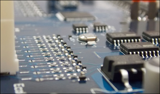
Image Courtesy: pcbgogo.com
SMT Process
The general SMT assembly process includes stencil preparation, solder paste printing, SMC (surface mount components) placement, reflow soldering, and inspection.
lStencil Preparation
A stencil is basically a sheet of stainless steel with cuttings that specify where solder paste is to be deposited onto the PCB in alignment with the placement of the components. The amount of solder paste deposited must also be carefully calculated.
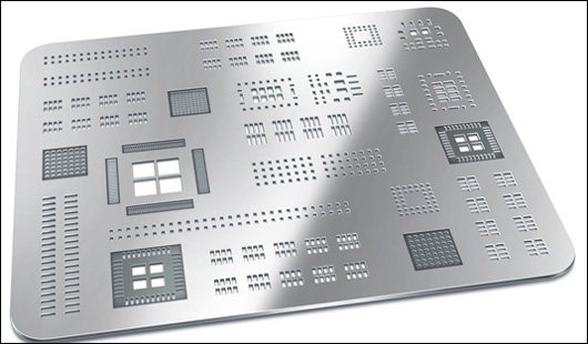
Image Courtesy: pcbgogo.com
lSolder Paste Printing
Once the stencil is set, the solder paste is added to one end which is then squeezed through with a squeegee. Once the solder paste is deposited the stencils are removed. The board is usually kept in a temperature-controlled environment, when the solder paste is applied you have to move to the component placement step before it sets.
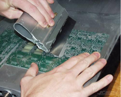
Image Courtesy: pcbgogo.com
lSMC Placement
The next step involves the placement of surface mount components via a pick-and-place machine. Assembly kits are prepared from the components and added to the pick-and-place machines on the production line. The pick-and-place machine will be programmed to place the components in their designated areas. This process is usually automated but can also be done manually, although with lesser precision.
lReflow Soldering
The next step involves reflow soldering. The PCB boards with the solder paste and components are passed through a reflow soldering machine. The board is then treated with controlled heating which will melt the solder and then solidify so solid solder joints are formed. The temperature must be carefully regulated so the board is not poorly soldered.
lInspection
The final step is the inspection of the printed circuit board. After soldering, the board is cleaned and then inspected to identify any faults or flaws. Then they are repaired or reworked on. Common methods of inspection include AOI, flying probe testing, and inspection via a magnifying lens, X-ray machine.
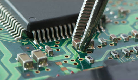
Image Courtesy: pcbgogo.com
Advantages of Surface Mount Technology
There are a number of advantages of SMT which make it the go-to method for PCB manufacturing and assembly.
§ The biggest advantage of SMT is the ability to incorporate smaller-sized components, most of the components used can be reduced by 60-70% in size, volume, and weight.
§ The entire process is automated as opposed to THT where some parts may need to be inserted manually. SMT parts can be installed on circuits using an automated pick-and-place machine.
§ Components used in SMT are more commonly available due to their large demand and are usually cheaper as opposed to through-hole components.
§ SMT components allow for the higher density of connections as there is more space for routing which would otherwise be occupied by holes.
§ SMT Components can be placed on both sides of the PCB
§ Higher signal transmission speeds and reduced RF interference.
§ Lower costs due to efficiency in process and simplified production line.
Disadvantages of Surface Mount Technology
While Surface Mount Technology is the more widely used method, there are cases in which it is not suitable and it has its own disadvantages.
§ SMT parts are harder to rework or repair. Due to their much smaller size, they prove to be difficult to locate, de-solder, replace, and re-solder.
§ Some through-hole components do not have equivalent parts for SMT usage and so you may have to work with the through-hole components instead.
§ Some through-hole components give better mechanical strength as opposed to SMT.
§ The complexity of the process demands professional training learning
§ Components are generally more prone to damage if not handled carefully.
§ Components that generate large amounts of heat are not suited to SMT as they may cause the solder to melt.
Conclusion
From the above discussion, we can conclude that SMT is a complex, articulated process. In order to ensure that you get the most efficient PCB, you must choose the right manufacturer. PCBgogo is such a manufacturer which is providing high-grade PCBs.
PCBgogo is one of the largest and most popular PCB manufacturers located in Shenzhen, China. Built over 2400 sqm of land, this company specializes in manufacturing high-quality PCB’s in low price. These boards are custom designed according to your needs. Just looking at the “product categories” PCBgogo specializes in, we realize how much they have expanded over the years. These categories include data communication, optical networking, medical treatment, industrial control, aerospace/military etc. just to name a few. You can check out their website pcbgogo.com for more information.
This article is originally published on electronicslovers.com and authorized to reprint on PCBgogo.
The original link: https://www.electronicslovers.com/2021/03/surface-mount-technology-all-you-need-to-know-pcbgogo.html
