
 日本語
日本語
 한국어
한국어

Flying Probe vs ICT: Which PCB Testing Method Is Better?
When comparing flying probe vs ICT, the best testing method depends primarily on production volume, PCB design stability, test-point accessibility, and the cost of developing a dedicated fixture.
Flying probe testing uses programmable moving probes and does not require a custom bed-of-nails fixture. It is flexible and economical for prototypes, engineering builds, and low-volume PCB assembly. In-circuit testing, commonly called ICT or bed-of-nails testing, requires a dedicated fixture but provides much faster test cycles, making it suitable for stable, higher-volume products.
PCBgogo provides both flying probe testing and ICT bed-of-nails testing for PCB assembly projects. This allows customers to choose a testing strategy that matches the current stage of their product - from initial prototypes to repeat production.
Flying Probe vs ICT at a Glance
| Comparison factor | Flying probe testing | ICT bed-of-nails testing |
|---|---|---|
| Probe system | Programmable moving probes | Fixed spring-loaded probes |
| Custom fixture | Not normally required | Required for each PCB design |
| Initial cost | Lower | Higher due to fixture |
| Test speed | Slower; points tested sequentially | Faster; many points accessed at once |
| Design changes | Easy to accommodate by updating the program | May require fixture modification or replacement |
| Best production volume | Prototypes and low-volume orders | Medium- and high-volume production |
| Test-point access | More flexible on dense designs | Requires sufficient accessible test points |
| Repeatability | Good | Very high |
| Typical application | NPI, prototypes, high-mix production | Mature and stable products |
The simple answer is:
Choose flying probe testing when flexibility and low setup cost are more important than test speed.
Choose ICT testing when production volume and throughput justify the fixture investment.
Consider using both methods during different stages of the product lifecycle.
What Is Flying Probe Testing?
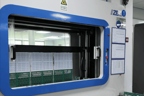
Flying probe testing is a fixtureless electrical test method in which several motor-controlled probes move across the PCB or PCBA. The probes contact selected pads, vias, component leads, and test points according to a test program generated from the board data.
Instead of contacting hundreds of test points simultaneously, the machine moves from one location to another and performs measurements in sequence.
Depending on the test program and available equipment, flying probe testing can help identify:
Open circuits
Short circuits
Incorrect resistance or capacitance values
Missing components
Component polarity errors
Poor solder connections
Connectivity problems
Differences from a known-good board
Because a custom fixture is not normally required, flying probe testing reduces initial setup cost and shortens preparation time. If the PCB layout changes, engineers can usually modify the test program without building an entirely new fixture.
These characteristics make flying probe testing particularly suitable for:
PCB prototypes
New product introduction, or NPI
Engineering validation builds
Low-volume PCB assembly
High-mix production
Products with frequent design revisions
Dense boards with limited conventional test-pad access
The principal disadvantage is test time. The probes must physically travel between test locations, so the test cycle is usually longer than ICT.
What Is ICT Bed-of-Nails Testing?
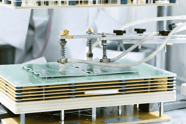
In-circuit testing uses a dedicated fixture containing an array of spring-loaded test pins. Because the pins resemble a bed of nails, ICT is also known as bed-of-nails testing.
Each pin is positioned to contact a specific test point on the PCB assembly. Once the board is correctly located and pressed against the fixture, the tester can access many electrical nodes without moving probes across the board.
An ICT system may check:
Opens and shorts
Resistance and capacitance
Component presence
Incorrect component values
Diode and transistor characteristics
Component orientation or polarity
Certain soldering defects
Power and ground connections
ICT provides fast, consistent, and highly repeatable testing. It is particularly effective at identifying manufacturing defects and isolating them to a specific net or component, which can make failure diagnosis and rework more efficient.
The tradeoff is the dedicated fixture. Fixture design, manufacturing, verification, storage, and maintenance create an upfront cost. The PCB must also provide sufficient accessible test points for the fixture probes.
As a result, ICT is generally best for:
Stable PCB designs
Repeat manufacturing orders
Medium- and high-volume PCB assembly
Products requiring short test cycles
Production lines where repeatability and throughput are priorities
The Main Differences Between Flying Probe and ICT
1. Fixture Requirements
Fixture cost is one of the most important differences in the flying probe vs ICT decision.
Flying probe testers rely on programmable probe movement, so they generally do not need a board-specific bed-of-nails fixture. This keeps non-recurring setup costs low.
ICT requires a fixture designed around the PCB layout and its accessible test points. A different PCB design normally requires a different fixture. Significant changes to test-point locations may also require modifying or replacing an existing fixture.
For PCBgogo ICT orders, customers may provide their own compatible fixture. If a customer does not already have one, PCBgogo can assist with purchasing the required fixture.
For fixtures containing fewer than 1,000 test points, the indicative purchasing cost is approximately US$59.28 per set. The final price is subject to the PCB layout, fixture structure, test requirements, compatibility, and engineering review.
2. Setup Cost and Per-Board Cost
Flying probe testing usually has a lower initial cost because there is no dedicated fixture to manufacture. However, its longer test cycle can produce a higher testing cost per board as order quantities increase.
ICT has the opposite cost structure:
Higher upfront fixture cost
Faster test cycles
Lower incremental testing cost at sufficient volume
The correct comparison is therefore not fixture price alone. Buyers should evaluate the total cost across the expected production quantity.
Break-even quantity = ICT fixture cost / (flying probe cost per board - ICT cost per board)
For example, if flying probe testing costs $0.80 more per board than ICT and the ICT fixture costs $59.28, the theoretical break-even point would be approximately 75 boards: $59.28 / $0.80 = 74.1 boards.
This is only an illustration. Actual costs depend on board complexity, test coverage, programming, handling time, fixture design, and order quantity.
3. Test Speed
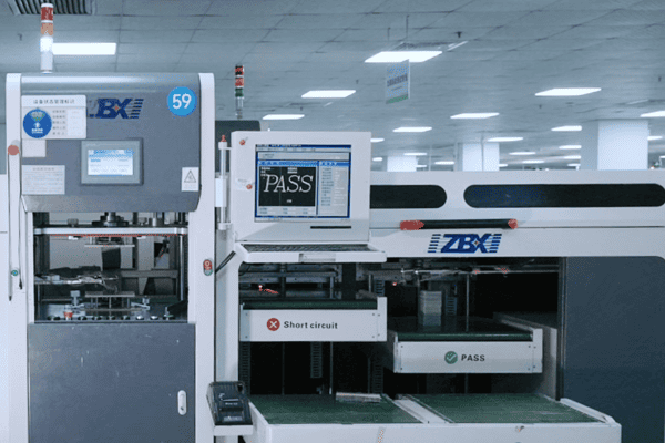
ICT is normally faster because its fixture can connect to many test points simultaneously. Once the test program and fixture are ready, individual test cycles may take only seconds for suitable assemblies.
Flying probe testing is sequential. Its cycle time increases with the number of nets, components, measurements, and probe movements.
The difference may not matter for ten prototypes, but it can become a production bottleneck across thousands of PCB assemblies.
4. Flexibility After a Design Revision
Flying probe testing is more adaptable to engineering changes. When test-point positions or circuit connections change, the test program can often be updated using the revised design data.
An ICT fixture is physically matched to the board. Moving a test point, changing the panel arrangement, or altering the PCB outline may make the existing fixture incompatible.
Flying probe is therefore valuable while the design is still evolving. ICT becomes more attractive after the layout and bill of materials are stable.
5. Test Coverage
Neither method automatically guarantees complete defect coverage.
Actual test coverage depends on:
Accessible electrical nodes
Test-point size and spacing
Component type and package
Circuit topology
Measurement limits
Test-program quality
Fixture and probe accuracy
Whether the board is tested powered or unpowered
ICT can provide extensive structural coverage when the board has been designed for fixture access. Flying probes can reach locations that may be difficult to include in a conventional fixture, particularly on dense or frequently changing boards.
However, electrical access is still essential. Hidden joints under BGAs, for example, may require X-ray inspection, while validating the complete operation of the product may require functional testing.
The strongest quality plan often combines electrical testing with AOI, X-ray inspection where appropriate, and functional testing.
Is Flying Probe Testing the Same as ICT?
The terminology can be confusing.
In a broad technical sense, flying probe testing can be considered a fixtureless form of in-circuit electrical testing because it measures circuits and components directly on the PCB assembly.
In PCB manufacturing discussions, however, ICT usually refers specifically to a fixed bed-of-nails system. Under this common usage:
ICT means fixture-based bed-of-nails testing.
Flying probe testing means programmable fixtureless testing.
How Production Volume Affects the Decision
There is no universal order quantity at which ICT automatically becomes the better choice. The correct threshold depends on test time, fixture cost, PCB complexity, forecast volume, and the expected number of design revisions.
As a practical guide:
Prototype and Engineering Builds
Flying probe testing is normally the better starting point. It avoids a dedicated fixture and allows the test program to follow design revisions.
Low-Volume and High-Mix Production
Flying probe testing often remains economical when many PCB models are produced in small quantities. A separate ICT fixture for every model may be difficult to justify.
Repeat Medium-Volume Production
Compare the total costs of both methods. A relatively inexpensive fixture and frequent repeat orders can make ICT economical sooner than expected.
High-Volume Production
ICT generally becomes preferable when a product is stable and test throughput is critical. Its shorter cycle time can offset the fixture cost across a large number of assemblies.
Avoid choosing solely by the size of the first order. If a product is expected to enter repeat production, its forecast lifecycle quantity is more relevant than its initial batch size.
Design for Testability Considerations
The test strategy should ideally be selected before the PCB layout is finalized. Adding accessible test points early is much easier than redesigning a densely routed board after production begins.
For better flying probe and ICT coverage, consider the following design-for-testability practices:
Provide test access to critical nets.
Keep test points away from tall components where possible.
Use clearly defined test-point coordinates.
Maintain sufficient spacing for reliable probe contact.
Avoid placing test points beneath components.
Include accessible ground and power test points.
Mark polarity and pin-one orientation clearly.
Keep reference designators consistent across the BOM, schematic, and placement file.
Consult the PCB assembly provider before freezing the layout.
ICT usually demands more structured test-point access because the fixed fixture must tolerate PCB, drilling, tooling, and assembly variations. Flying probe systems offer more positioning flexibility, but accessible and well-designed targets still improve test reliability and cycle time.
Choosing Flying Probe or ICT at PCBgogo
PCBgogo supports both testing methods, so the selection can be based on the needs of the product rather than a single fixed process.
Choose PCBgogo flying probe testing when:
You are building prototypes or a small batch.
The PCB design may change.
You want to avoid a dedicated fixture.
Setup flexibility is more important than maximum throughput.
You manufacture several PCB variants in limited quantities.
Choose PCBgogo ICT bed-of-nails testing when:
The PCB design is stable.
You expect repeat or volume orders.
Short test cycles are important.
The assembly provides adequate test-point access.
You want consistent, repeatable production screening.
For ICT, customers can provide their own test fixture or ask PCBgogo to assist with fixture purchasing. Fixture costs vary depending on the number of test points and specific testing requirements. Please contact our engineering team for a detailed quotation.
Flying Probe vs ICT: Final Recommendation
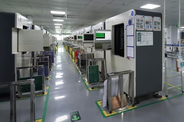
The decision between flying probe vs ICT comes down to flexibility versus throughput.
Flying probe testing offers low initial cost, quick adaptation, and no conventional bed-of-nails fixture. It is the practical choice for prototypes, low-volume orders, high-mix production, and designs that are still changing.
ICT requires a dedicated fixture, but its speed and repeatability make it more cost-effective for stable, repeat production. The fixture should be viewed as a one-time investment that is distributed across the product's expected manufacturing volume.
For many projects, the most efficient strategy is to begin with flying probe testing and transition to ICT once the design is stable and production volume grows.
PCBgogo can support both stages, helping customers maintain electrical test coverage from prototype PCB assembly through repeat manufacturing.
Frequently Asked Questions
Which is better, flying probe or ICT?
Flying probe is generally better for prototypes, small batches, and changing PCB designs. ICT is generally better for stable, medium- or high-volume production because its test cycle is faster.
Does flying probe testing require a fixture?
Flying probe testing normally does not require a dedicated bed-of-nails fixture. Movable probes are controlled by a test program and travel between selected points on the PCB assembly.
Why is ICT faster than flying probe testing?
An ICT fixture provides simultaneous access to many test points. Flying probe testing must move its probes between points and perform measurements sequentially.
What defects can flying probe and ICT detect?
Both methods can detect defects such as opens, shorts, incorrect component values, missing components, polarity problems, and certain soldering faults. Exact coverage depends on board accessibility, equipment capability, and the test program.
Can ICT replace functional testing?
No. ICT focuses mainly on component-level and circuit-level manufacturing defects. Functional testing verifies whether the completed assembly operates as intended under defined conditions. Many products benefit from using both.
Can I reuse an ICT fixture?
Yes, an ICT fixture can generally be reused for repeat orders of the same PCB design. Changes to the PCB outline, panel, component layout, or test-point positions may require fixture modification or replacement.
How do I calculate whether an ICT fixture is worthwhile?
Compare the fixture cost with the per-board saving achieved by ICT: break-even quantity = fixture cost / per-board testing cost difference. Production forecasts, future design revisions, fixture maintenance, and test throughput should also be included in the decision.





