
 日本語
日本語
 한국어
한국어

Chamfer CNC Machining: Design, Tools and Cost Guide
QUICK ANSWER Chamfer CNC machining creates a flat angled surface where two faces meet, most often to remove a sharp edge, guide assembly, or prepare a hole for a fastener. A 45-degree chamfer is common, but the best size, angle, tool, and tolerance depend on function, material, tool access, and inspection requirements.
What Is Chamfer CNC Machining?
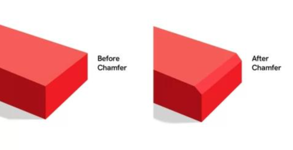
Chamfer CNC machining is the controlled removal of material along an edge to form a straight sloped face. Unlike a fillet, which is rounded, a chamfer has a measurable width or leg length and an angle. On drawings, it may appear as C0.5 × 45°, which specifies a 0.5 mm chamfer at 45 degrees.
Chamfers eliminate hazardous burrs, help shafts enter bores, protect corners, create a lead for threads, and let flat head screws sit flush when designed as a countersink. Repeated edge breaks can also improve product appearance.
Which Chamfer Angles and Sizes Work Best?
The best chamfer angle follows the feature's job, not a universal rule. Forty-five degrees is widely used because a standard chamfer mill can create equal legs efficiently, but 30- and 60-degree features are useful when assembly geometry, clearance, or a mating component demands them.
| Chamfer choice | Typical purpose | Design implication |
|---|---|---|
| Small edge break | Remove burrs and sharpness | Keep the tolerance practical and identify only required edges |
| 45 degree chamfer | General edge treatment and assembly lead | Often efficient with standard tooling and simple inspection |
| 30 or 60 degree chamfer | Specific lead-in, clearance, or interface | Confirm tool availability and state the angle explicitly |
| Countersink | Seat a flat head fastener | Match the fastener angle and control the finished diameter or depth |
Size the chamfer from function. A cosmetic edge break should not receive the same tight tolerance as a sealing interface or fastener seat. Very small chamfers can disappear within burr variation, while oversized chamfers may reduce wall thickness or shorten a bearing land.
How Are Chamfers Cut on CNC Machines?
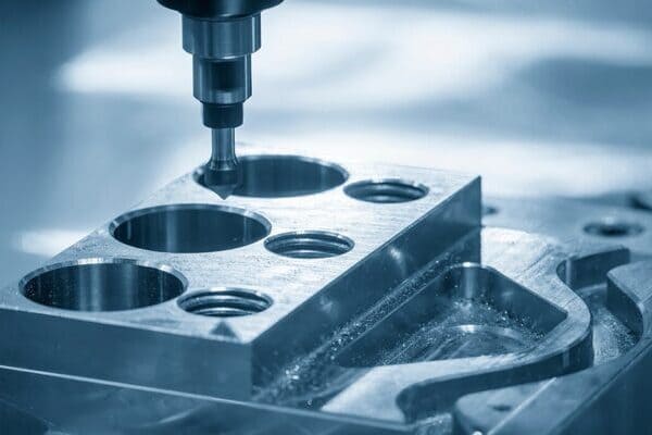
CNC chamfers are usually machined after the main geometry so the finishing pass can follow the completed edge. The programmed toolpath controls the cutter position and depth, while cutter angle establishes the sloped face. External profiles are traced along their perimeter, and hole chamfers are commonly produced with a circular move or countersink cycle.
Chamfer mill: A dedicated angled cutter is the usual choice for repeatable external edges, pockets, and accessible holes. One tool can often machine several chamfer widths when its cutting edge is long enough.
Countersink tool: This tool is designed for holes, especially where a flat head screw must seat correctly. The included angle must match the fastener requirement.
Spot drill: A spot drill can add a light hole chamfer, but its geometry must suit the final callout.
End mill or ball end mill: A standard cutter can contour an unusual angled face, although the longer toolpath usually costs more.
Runout, rigidity, tool wear, workholding, and burr behavior affect consistency. Stainless steel and titanium demand close attention to heat and wear, while plastics need sharp tools and heat control.
How Should a Chamfer Be Specified on a Drawing?
A good chamfer callout states what must be made and measured without forcing the machinist to guess. Use the drawing convention required by your organization and specify the count when the same feature repeats.
State size and angle: Use a clear callout such as 4X C0.5 × 45° for four identical chamfers. If the drawing uses another dimensioning method, keep it consistent throughout the part.
Identify the affected edges: Attach a leader to the exact edge or use an unambiguous general note. Avoid saying break all edges when some corners are datum, sealing, or mating features.
Separate edge break from deburring: Deburr removes loose or sharp material, but it does not automatically create a controlled geometric chamfer. Dimension the feature when width or angle matters.
Apply a functional tolerance: Tolerance the width, angle, diameter, or depth according to how the part assembles and how the feature will be inspected. Excess precision adds tool compensation and measurement time.
ASME Y14.5 provides the common language for dimensioning and tolerancing on engineering drawings. ISO 13715 covers edges of undefined shape, while ISO notes that geometrically defined edges such as 1 × 45° follow the general dimensioning principles in ISO 129-1. Use the standard named by the drawing rather than mixing conventions.
Chamfer vs. Fillet vs. Bevel: Which Edge Treatment Should You Use?
A chamfer is usually the economical choice for an assembly lead or controlled edge break, while a fillet is better when a smooth radius is needed to reduce stress. Bevel is a broader term for an angled face and often describes a larger feature that extends across a substantial portion of the edge.
Choose a chamfer: Use it for safe handling, fastener clearance, thread entry, locating features, and straightforward inspection. Straight toolpaths and standard angles usually support efficient machining.
Choose a fillet: Use a radius on load-bearing or fatigue-sensitive transitions where a sharp change in section would concentrate stress. Internal fillets are also constrained by cutter radius.
Choose a bevel: Use the term when the angled face is a major design feature, but dimension its angle and extents clearly. Do not rely on the word bevel alone to communicate manufacturing intent.
How Can Chamfer Design Reduce CNC Cost?
Cost falls when chamfer CNC machining uses standard tools, accessible edges, realistic tolerances, and a consistent feature strategy. Every special angle, extra setup, hidden edge, and inspection requirement can add programming or machine time.
Standardize angles and widths: Reuse one or two chamfer sizes across the part where function allows. This reduces tool changes, offsets, and opportunities for inconsistent interpretation.
Design for cutter access: Provide clearance around the edge and avoid chamfers trapped behind walls or inside deep narrow pockets. Restricted access may require long reach tooling, another setup, or multi-axis machining.
Chamfer only valuable edges: Blanket requirements increase cycle time and may unintentionally alter datum or mating edges. Mark safety, assembly, and cosmetic edges deliberately.
Avoid unnecessary tight tolerances: A general edge break rarely needs the tolerance of a precision seat. Match inspection effort to the consequence of variation.
Share both CAD and drawing data: The 3D model communicates geometry, while the drawing identifies critical dimensions, surface finish, datums, edge notes, and acceptance criteria that may not survive model translation.
How Should Chamfers Be Inspected?
Chamfer inspection should verify the characteristic that controls function. Width can be checked with optical measurement, a comparator, or a suitable gauge. Hole chamfers and countersinks may be evaluated by diameter, depth, angle, or fastener seating, depending on the drawing.
A visual check can suit noncritical deburring, but it cannot prove a tight geometric requirement. Define whether the callout controls one leg, face width, included angle, or intersection diameter. For production, approve a first article and monitor tool wear.
How PCBgogo Supports Chamfered CNC Parts
PCBgogo can support chamfered CNC parts within a broader one-stop manufacturing workflow for electronics products. Its public service information presents CNC machining alongside PCB fabrication, PCB assembly, component sourcing, and UV printing, which is useful when a project combines a machined enclosure, bracket, heat sink, or fixture with a circuit board.
Engineering review before production: PCBgogo states that customer orders are checked by engineers. For a chamfered part, provide the 3D model, controlled drawing, material, finish, quantity, critical edges, and inspection needs so manufacturability questions can be resolved before cutting.
Prototype and scaling support: The combined manufacturing model helps hardware teams validate mechanical fit and board integration during prototyping, then coordinate revisions as demand moves toward batch production.
Quality-focused operations: PCBgogo states that its factories follow ISO 9001:2015 and IATF 16949 quality management systems and meet UL, REACH, and RoHS requirements for its manufacturing operations. Project specific requirements should still be confirmed during quotation.
Simpler supplier coordination: Using one partner for relevant mechanical and electronics work can reduce handoff errors between enclosure dimensions, mounting holes, connector openings, and the PCB assembly that must fit inside.
For an accurate quotation, ask PCBgogo to review chamfer tool access, standard cutter options, tolerance strategy, deburring scope, surface finish, inspection method, and expected quantity. This turns a generic edge note into a manufacturable requirement and helps avoid paying for precision the design does not need.
Frequently Asked Questions About Chamfer CNC Machining
What is the most common CNC chamfer angle?
Forty-five degrees is the most common general-purpose angle because it creates equal legs and is supported by widely available tooling. Use another angle when a fastener, mating feature, or functional lead requires it.
Is a chamfer the same as deburring?
No. Deburring removes unwanted sharp material, while a chamfer is a defined angled feature. A light edge break may achieve both goals, but dimension it if its geometry matters.
Can CNC machines chamfer internal holes?
Yes. Accessible holes can be chamfered with a chamfer mill, countersink, or suitable spot tool. Deep holes, cross holes, and back side edges may need special tools or another setup.
Does a chamfer make a part stronger?
A chamfer can protect an exposed corner and prevent handling damage, but it is not usually as effective as a fillet for reducing stress concentration at a loaded transition. Choose the edge form from the load case.
What files should I send for a CNC chamfer quote?
Send a native or neutral 3D CAD file plus a controlled PDF drawing. Include material, quantity, finish, chamfer callouts, general edge treatment, critical tolerances, datums, and inspection expectations.
Design the Edge Around Function
Successful chamfer CNC machining starts with a simple decision: define which edge needs an angled face and why. Standardize practical angles, preserve tool access, specify measurable requirements, and reserve tight tolerances for features that affect fit or performance. When the design is ready, PCBgogo can review the mechanical requirements alongside the PCB and assembly needs of the complete product.





